apu02 Cables
To connect the Moxa with my apus I had to customize the cables I got from aliexpress.
Till now I never had to create my custom serial console cable, so to me this was a new experience.
Finding the combination
I first had to find out the correct combination of cables since it did not work with these cables right away so I put a breadboard in between the cables.
 To connect the wires to the breadboard I did crimp connectors to them.
 For this I used a crimping tool and a set of connectors.
 Then the fun started, based on the information from pcengines and from the Moxa CN2510 Manual about the expected wiring I tried to apply it to the existing cable.
Check the cable
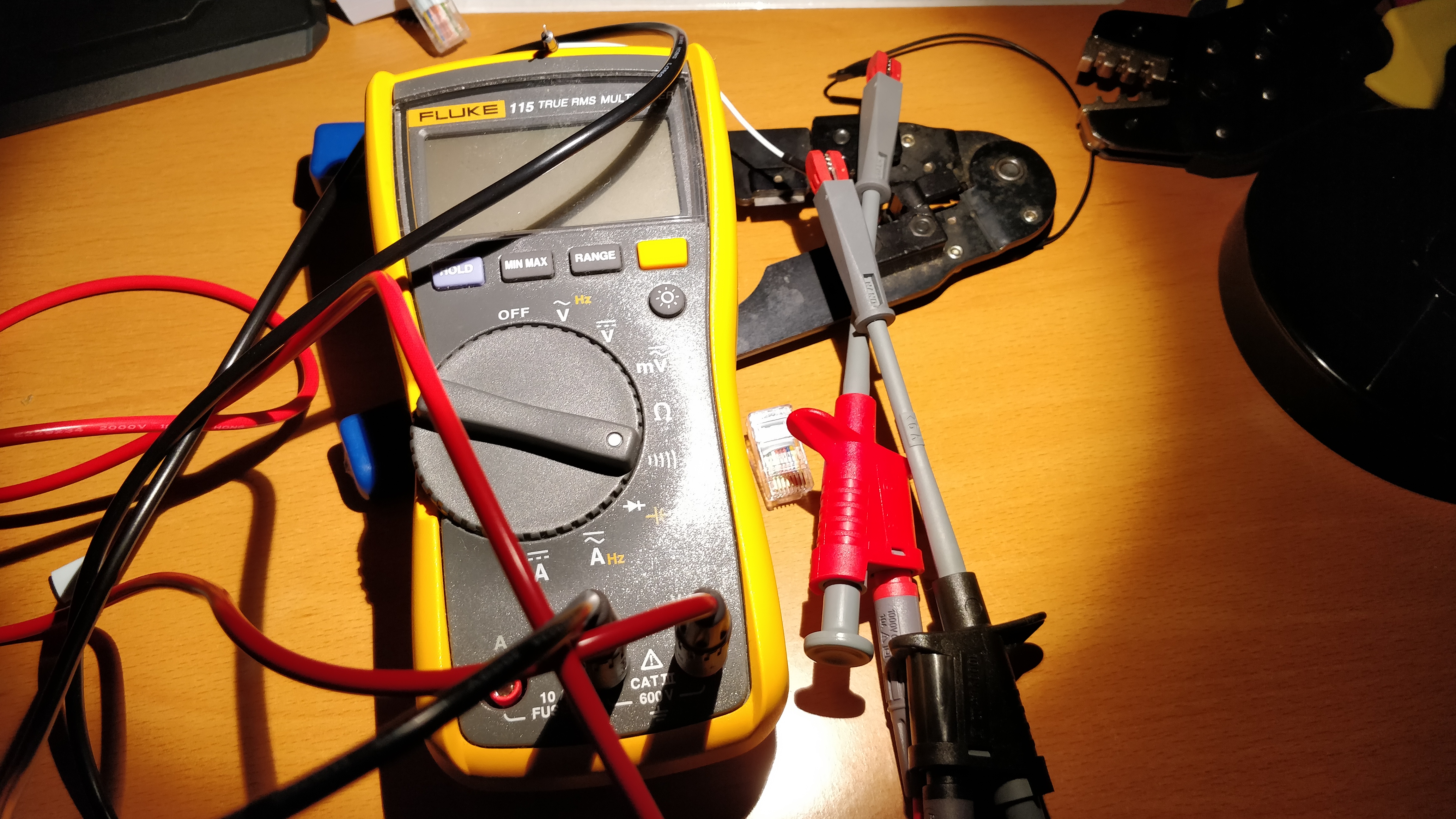
I checked the wiring using a Fluke 115.
Pin combinbations
Finally I had the correct wiring transferred to my cable.
For the RJ45 the Moxa needs the following wiring:
| Pin | Collor | Signal Type |
|---|---|---|
| 1 | transparent | DSR |
| 2 | green | RTS |
| 3 | white | GND |
| 4 | orange | TxD |
| 5 | brown | RxD |
| 6 | red | DCD |
| 7 | blue | CTS |
| 8 | yellow | DTR |
From the DB9 Connector these colors are assigend to the follwing Pins, the apu expects a wiring of a null modem cable.
| Pin | Collor | Signal Type |
|---|---|---|
| 1 | brown | DCD |
| 2 | red | RxD |
| 3 | white | TxD |
| 4 | green | DTR |
| 5 | orange | GND |
| 6 | blue | DSR |
| 7 | transparent | RTS |
| 8 | yellow | CTS |
The mapping
Based on this information I came up with the following mapping:
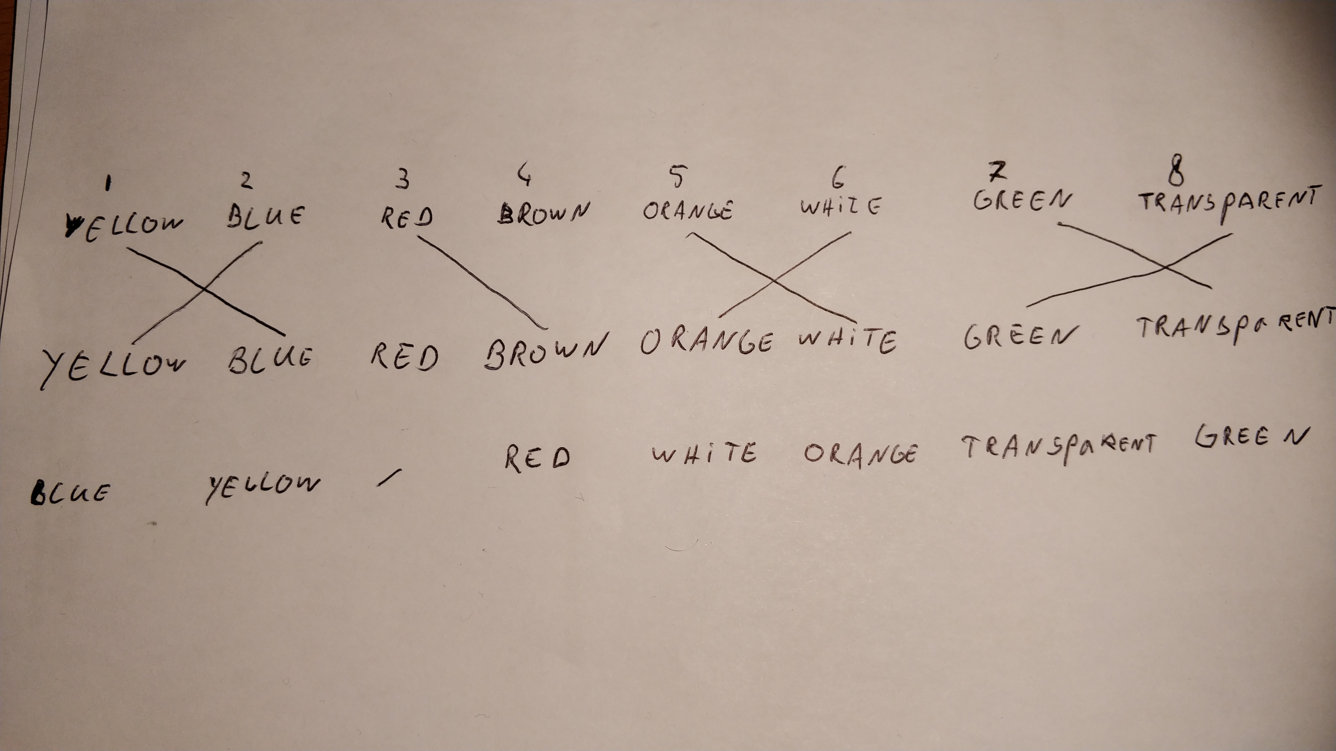
| Pin | Collor |
|---|---|
| 1 | blue |
| 2 | yellow |
| 3 | - |
| 4 | red |
| 5 | white |
| 6 | orange |
| 7 | transparent |
| 8 | green |
The the RJ45 crimping tool came to use.
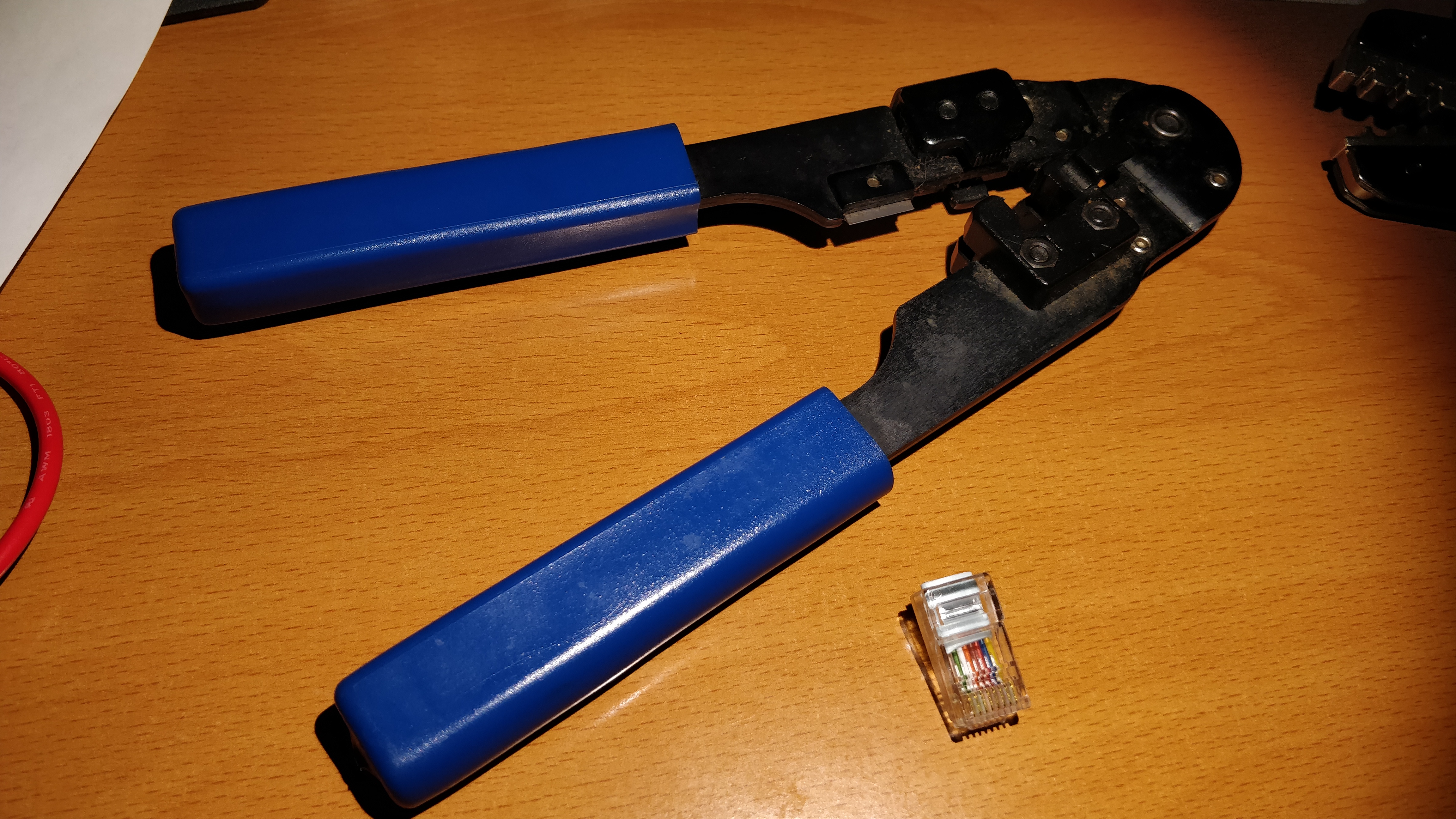 And the custom cable got produced.

No comments to display
No comments to display